• Welcome to the Contour Enthusiasts Group, the best resource for the Ford Contour and Mercury Mystique.

    You can register to join the community.

3 alternators no charging

cclngthr

CEG'er
Joined
Sep 18, 2014
Messages
293
Location
Puyallup wa
1998 Contour: V6 automatic power everything

Alt crapped out last month when ATF from transmission sprayed everywhere. Replaced trans, alt and PS pump belts and tensioners. First alt replaced (shop is doing the work under warranty) had bad bearings/windings. It was charging somewhat but not enough. Brand was Ultima (reman/new) from O'Reilly. Shop went through 2 others that appeared to test ok on the bench, but only put out 12 volts on the car.

We also replaced the battery cables with slightly larger ones, better ground cables as well. However on the 4 power leads from the junction boxes were bundled together when they redid the wiring; and now the alt isn't charging. I find it odd that 3 alternators are not working in a series like this.

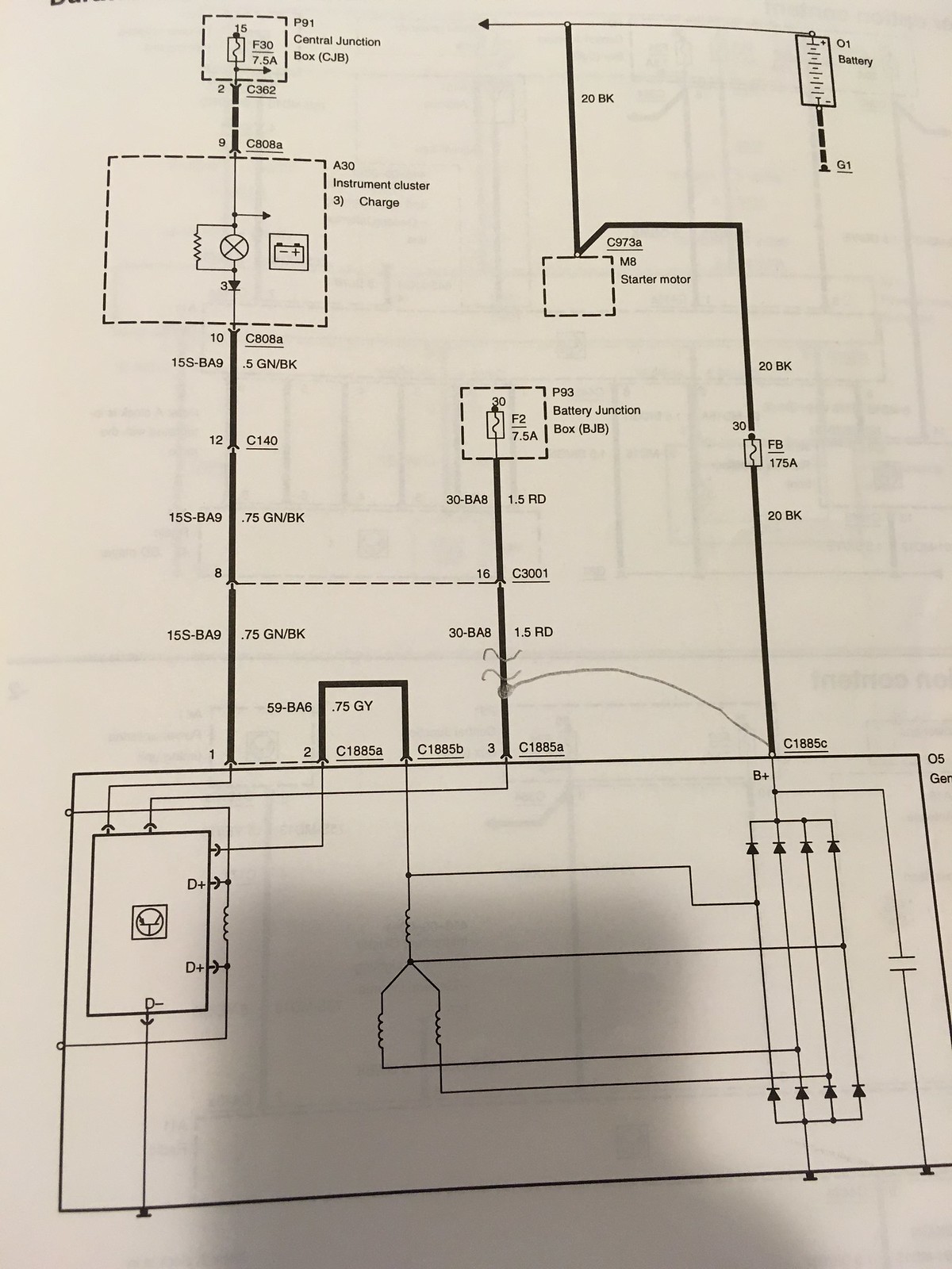
What I am wondering is if the bundled wires feeding power to the junction boxes may be part of the problem where the amperage is dropping just enough to not send the signals to the alternator to excite the rectifier in the alt. Is it possible that there could be resistance in that harness somehow (I don't see any wiring damage to indicate that. Also, I only see the red wires, not the white with black tracer wire.

Edit:

Did find the problem. In the instrument cluster, there is a communication bus line from the PCM and that monitors what is going on with the powertrain, airbag system, charging system and ABS (if that is installed). On the charging system, the cluster sends data back to the PCM on status of the charge and if it does not see it, the computer will either send data to the alternator to ramp up the charge; or turn it off. What it was doing is ramping up the alternator to full field 100% of the time. That shorted out the alternators immediately. On the oem alt, it did not short it out because the VR was able to handle that.
 
Collectively we have seen this often with rebuilt alts - they just don't work once installed, and the bench testing method does not test it correctly. Have you tried a 100% new unit yet? THat is typically the fix - it was for me last fall.

As for wires, that was a good step replacing the pos & neg large wires with new cables. If you are worried about resistance, get a volt meter and measure the wire resistance. Bundling or zip tie-ing them together shouldn't matter.

I called the shop and they said all of them have been remans. However I want the shop to check out the wiring harness that goes from the junction block to the battery. Satya had said that harness goes bad easy.

Last year I was lucky in getting a rebuilt unit that was able to charge well. The first one overcharged and the ecu turned the alt off at high rpm. The second one worked. This time, atf was spraying everywhere and destroyed The alt and when the trans was replaced the alt also was swapped out. It charged for maybe a week or 2 and it started grinding. 3 alts later, still no charge
 
I sold both rebuilt and new alts there for a while and fully 20% or so of them are bad right out of the boxes, it's a HUGE problem for the parts stores. 3 in row is a bit unusual but BTDT too. Much of the issue is that the builders absolutely refuse to use quality regulators, they'd much rather give that money to the CEO. The cheap Chinese regulators often fail in minutes, I rebuild my own alts and ALWAYS use much more expensive regs and it shows, they keep on working right.

It's just not that hard to build an alt but the people doing it are not very smart, they commonly never even turn the pulleys to see if something might be dragging, that being one of the major problems and an idiot can catch that. Or maybe not eh? I saw fields shorted to cases and bad internal grounds on them all the time; they simply do not care and part of China's getting the upper hand on the USA in every way they can.

Testing them is greatly problematic too, the quick connectors used on todays' alts work great but only for 2-3 times, once you start reconnecting them over and over in testing the test leads go bad quickly and most of the parts stores do not cycle them out for new like they should as after 5 times use they will be bad again and the stores get charged for that.


I am having the shop who is doing it (it is under their warranty) try one from a different brand thsn what they have been getting. The reason why they are doing it is they had to swap it out because atf from the transmission went everywhere and the connector to the VR cracked. Dell at the shop who is their electronic diagnostician went through the wiring several times and did pull the harness apart to see if that failed. He sent pictures to me and the wiring is intact and in good condition. The alternator they put in last month was working but it was also backfeeding in reverse (it would provide a charge but it would also pull power from the battery at certain rpms). It also was grinding loudly as well.They are going with a local rebuilder in getting a new one, if this one they ordered Saturday fails.

My thinking is the car really is fussy on voltages and it wants to see a particular brand of regulator to work right. The local builder said he can load up the alternator full field and check the VR in the specific voltages the car produces.


I had a local rebuilder tell me (who has many years experience) that it is best to go with an OEM (new or reman) alternator. The VR has a sense circuit (the 98's have a constant power on one leg of the voltage regulator and the second leg is the sense circuit leg). The sense circuit according to his schematic goes through the cluster, which there is a communication circuit to the pcm where the pcm monitors the alternator that way. He also said that the voltage regulator is a specialty unit that needs to be designed one way to have the PCM communicate with it.

I went with an OEM Motorcraft unit.
 
Found why the alternator blows itself up.

Inside the cluster is a circuit with a diode that is part of the charge sensing circuit that is blown. The faulty diode is making the PCM think the alternator is not charging which it tells the voltage regulator to ramp up the rate of charge.
 
Interesting. That is the first time I've heard of that happening, good to know.

I see the diode on the wiring diagram, but it is truly just the regulator & diode not working right - no PCM interaction. What made the diode fail?

42468947245_7f9617d806_h.jpg
 
Interesting. That is the first time I've heard of that happening, good to know.

I see the diode on the wiring diagram, but it is truly just the regulator & diode not working right - no PCM interaction. What made the diode fail?

42468947245_7f9617d806_h.jpg

The PCM does handle it in a back door method through the cluster. The wiring diagram there shows the charging system circuit, but what it doesnt show you is the interaction with the PCM. That is done through the cluster itself. Another diagram that has the cluster schematic does show the connection from the PCM to the sense circuit. Dell and Rob noticed it when they backprobed the wiring at the CJB, alternator, and cluster. They saw the low signal sense circuit at the CJB but also the same value at the cluster input, BUT did see at the output of the sense signal circuit at 100% as well as the 100% cycle at the alternator. The low signal was because the system wasn't seeing the high output of the sense signal from the alternator.

Retesting the voltage regulator with a adjustable sense tester did find the voltage regulator operated normally and they discovered a technical bulletin about it to replace the cluster if the voltage regulator is at constant full field is present or alternator shorting out quickly.

I don't know what made it short out. Josh thinks it has been like that for a while and through digging into it, found the bad diode. It is possible to replace the diode which they are attempting, but ordered one just in case if that did not work. The test tools they used were the lab scope, with multiple channel inputs and the high end scan tool to see the data from the cluster module.
 
How the system works is at the cluster, the PCM monitors it through a back door smart system indirectly and IF the alternator is overcharging, the PCM is telling the cluster to turn off the alternator. Last year when I had a bad alternator replaced and got one that had a bad VR, when I revved the engine past a certain point, the alternator would automatically turn OFF. The threshold is anything past 16.4 volts the cluster cuts the sense circuit offline from the CJB. Below that, it will keep the circuit live and connected. The shop did the work last year and had never seen an alternator turn off if the rpm was higher. The alt light in that condition was bright when the voltage was over 15.5 but dim if the voltage is under 12 volts.
 
WOW! Thanks, it is a tangled mess when you dig in!

Tangled, yes, but now it is a protocol in testing these systems. We have to realize in modern cars built after 1986 that the PCM is involved in many things, and testing the operation involves more than a simple field test. It involves expensive equipment and tools. The lab scope is $10,000. Scanners are also about that same price that have the ability to access body control functions, and can tap into the controls by electronically switching off and on various control systems. With this equipment, I have the ability to activate injectors, IMRC, alternator duty cycles, A/C, electric power steering devices, cooling fan and a buttload of other tied in stuff.

I ran into a car with the same issue years ago on a 1986 Subaru. It would not communicate back to the PCM from the alternator, and the alternator would mysteriously turn itself off. In that case, the cluster was interfering with the system as well. Had to replace the cluster as well as a shorted wire unrelated to the charging system.
 
What we are going to do is replace the entire cluster assembly, because we found the backing of the circuit board separating from the hard board. Rob thinks not only the diode went bad, but also other parts of the circuit board is bad. That cluster too is tied into the transmission control module (and speed sensors) among other things. Might have been causing trouble with other systems and it is easier and cheaper to swap it out.

Once Josh sends me some pictures, I will post them.
 
No Title

Back of the existing cluster. Note the 2 diodes with arrows. Both diodes function in how the PCM communicates with the alternator.
 

Attachments

  • photo18232.jpeg
    photo18232.jpeg
    102.5 KB · Views: 1
I think somebody is thoroughly confused about that cluster, it has ZERO feedback to the PCM as far as the alt goes. The alt there is 100% standalone with no PCM control, what you are looking at is the later version of the exact same alt output = 12 volts normally in the system switching mechanism that Ford has used since the '60s. It's how the charge light in that schematic gets turned out. Thinking it may cut the field on/off too. I've rebuilt 3-4 of those alts with no concern for any PCM influence at all and they work perfectly when done. I used to use them on late Tempos as well, same alt other than the casting mounts. Again, NO PCM input on those either.

PCM control did not begin on 3G alts until like '00 or later.

And WHAT transmission control module? (post #15), that trans if ATX is a simple CD4E, which has no such thing on it. I detect a load of BS in much of that posting and in several others as well.

I've been building the alts for some 30 years and often fix them for as little as 10 cents worth of solder, and that on PCM controlled 6G alts. Many fixes done for under $10 to last for years. The alts are simply not that complicated.............

The rebuilder I use also confirmed that the correct voltage regulator used on the late model 98's use a unique sensor circuit tied to the pcm. A regular VR won't work on it. He has been rebuilding alternators and starters for 35 years.

The tach on the late 98's uses the signal from the PCM, not the crank signal, and that is also tied in with the speedo, alternator circuit, and other circuits in thw cluster.

This is not the E0 98 vehicle, which uses a completely different wiring circuit system. Ford changed the wiring in 3/98 and changed the circuit board in the cluster for that 9 month period only (it was used 1 year). No other cluster can be used, since it was changed so earlier boards won't work on it.

Shop at first received a E0 98 (pre 98) cluster which has a very different circuit board and it would not work because the difference is too great for the system to work correctly.

The PCM does get the alt signal through the cluster, and monitors through it. Last year, I had an alt changed and that one was overcharging, and what the system was doing was shutting off the alternator once the voltage from the alt reached 16.7 volts. Under the "old style" the alt should not shut off if it is overcharging when the VR is defective. It was doing that through the cluster monitor (a Pico scope was used to monitor the pulse width signal from the alternator).
 
Again I do NOT agree. I have one of the ones you call out by build date (4/98) and currently using a normal non-PWM regulator off of one of the Tempos I spoke of ('94 model). Been running like that for years. The cluster circuit there CANNOT carry PWM, it would then not work right, PWM requires BOTH a voltage sense AND a separate PWM output wire from PCM or two total to work, where is the other one? The system clearly uses 12 volt power from a fuse (F30) then to the bulb and then to regulator, the regulator meets it with more DC voltage. The way it works is that the two sides offset each other in equal power (the resistor and diode there are simply dampers) to put out the light and Ford has used that exact same circuit since the '60s, look at the various diagrams. As well, the alt does NOT send back in pulse, it receives that way only, the PCM is what sends any possible PWM control pulse there, it then reads simple voltage from the alt to correct. Even true PWM alts do not send back to a cluster (or anything else) in PWM, it is receive only there. So, just what was somebody reading there? Simple voltage. Pico scope.......(shaking head sadly).

I have wiring schematics from '95-'99 and that part at the cluster shows exactly the same on all. Just looked each year up. The only regulator difference is some are soft start and some are not, they interchange.

I work on 6G PWM systems all day long and no need for expensive equipment like that, they are easy enough to get working back right like they are. I also tested both non and PWM alts until I saw stars and clearly remember the different setups need to test each. The test machine PWM setup was extremely sensitive to failing the alts in testing after like 5 uses and I was always correcting the test harness to work right, it was a pain in the butt but nobody else in the shop knew what to look for.

Under your theory, the voltage regulator would be able to "adjust" if voltage at the sense wire was at 12-14 volts. It wasn't doing that. The amperage output at the altermator was at a constant 120 amps at 14 volts. The volt meter at battery showed 14 volts, but the pico scope with amp probe/clamp showed the output at the alternator without a load was at a constant 120 amps regardless of rpm. At the battery, amperage to the battery without loads was 80 amps. Still had a 14 VOLT reading on the volt meter at battery.

Upon startup, alt WAS working under full field for 15 minutes before the alternator shorted out. Battery was not seeing the amperage, which under testing, the wiring tested ok. The main fusable link and wire was bench tested at 150 amps with no problem. Sense wire and power wires tested fine too. The problem was the cluster being shorted out. All 3 alternators, even one new alternator did this.

The maximum amp charge to the battery should be no more than 4.5 amps at any time. Any more than that, you burn up the battery. Maintaining the charge, the alt charge to the battery should be .8 amp.

You have to have a wiring diagram of the entire cluster, and how everything is integrated with it and how things are tied together.
 
Back
Top