
dyaballikl
CEG'er
Ok, so I've finally been a member for over a month, so I can finally start posting my how-to's. Here's #1.
With this mod, you'll have to hold your bright flasher in so the brights are on in order for your starter to be able to be powered. This is a very effective, and cheap, way to secure your car from being stolen.
Pros: Cheap (around $6-$15), easy (takes about 45 minutes for a n00b), effective.
Cons: Telltale signs of security system for those who've seen your car start (they notice your brights are always on when you start your car), definitely a con for cons, though!
Items needed:
1 30 Amp auto 4 or 5 prong relay (Bosch design)
2 feet of 14 gauge automotive wire (preferably 2 colors)
2 feet of 18 gauge automotive wire (preferably 2 colors)
4 female quick disconnect connectors (for 14-18 gauge wiring)
2 14 gauge compatible wiring couplers (connects 2 wires)
2 wire taps (optional)
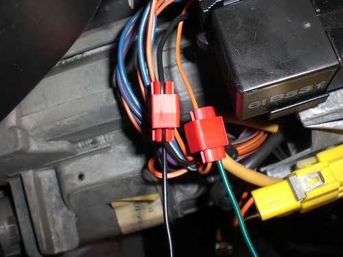
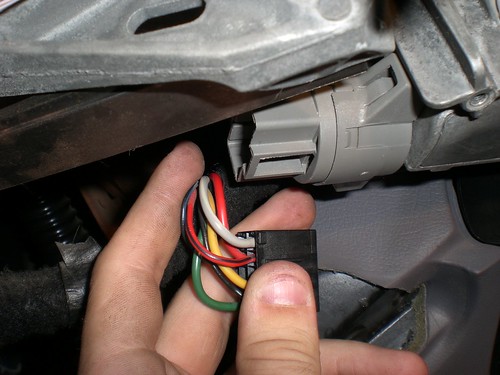
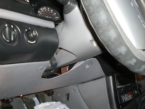
1. Remove the plastic case on the bottom side of the
steering column (where the ignition is) by removing
the 3 screws underneath it then gently pushing it out.
Locate the wires that come from the switch on the left
that controls the vehicles brights (blinkers also).
Find the orange wire with the yellow stripe, this is
the wire that gets power when you pull the handle to
flash your brights. If you're using wire taps, tap
into this wire with 1-1.5 feet of 18 gauge wire
(preferably green). Now, in the same bundle of wires,
find the black wire, we'll use this as the ground for
the relay coil, so tap into that with another 1-1.5
feet of 18 gauge wire (preferably black). If you're
not using wire taps, you can simply strip the wire and
pull back the insulation, then wrap your wire around
the exposed wiring. Soldering is recommended for that,
and electrical tape or heat shrinking is required.
This is what you should be looking at now:
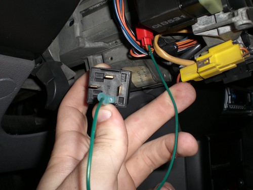
2. Now, take the other ends of each of those wires,
and crimp on your female quick-disconnect connectors.
When we say "female" connector, this does relate to
human anatomy, so the female is the one that recieves
the male end of the connector. If the connector's
you're using aren't insulted, be sure to tightly and
thoroughly wrap them up with electrical tape after
crimping them on. Now, take your wire that's connected
to the orange/yellow one (mine's green), and put it on
the #85 prong of your relay (you may have to put a bit
for force to get the connector on there, but that's
good, that ensures a strong connection. If it's very
loose, that's bad).
Your relay maybe slightly different from mine. You may
have 5 prongs, where mine has four. The prongs are all
numbered, and the only ones you need to be concerned
with are 85, 86, 87, and 30. If yours has an 87a, just
use electrical tape to wrap it up.
3. Now, connect your black wire (the ground connected
to the black wire in the bundle) to the #86 on the
relay. Now, we've got the switch (headlight flasher)
wired into the coil of the relay. Now we just need to
attach the power for the device. First, we need to
remove that lower plastic panel. Start by twisting the
foot illumination light from behind and pull it out.
Then, using a small flat electronics screw driver or
razor blade, pop out the plastic covers over the top 3
bolts that hold tha panel on.
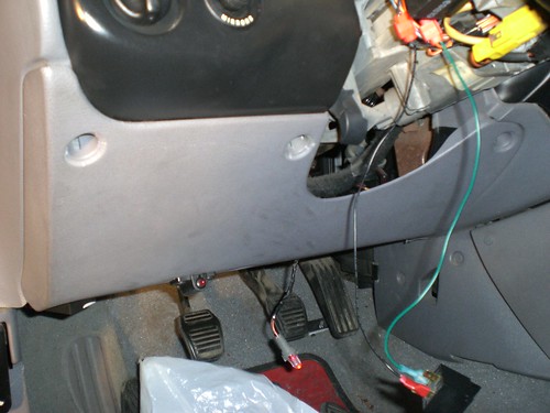
4. Then remove the top 3 and lower 2 bolts, which have
7mm heads. The panel should come right down. Once off,
check out the back of the ignition. It'll be a long
steel piece, which a black connector on the back. This
is where the starter wire comes from.
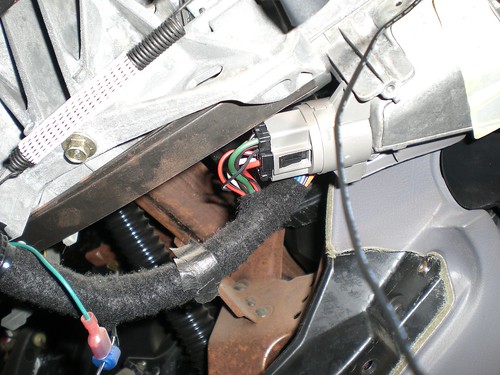
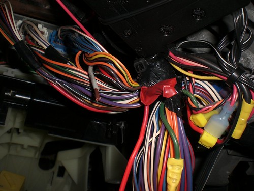
5. Now, what you want to do is cut the starter wire
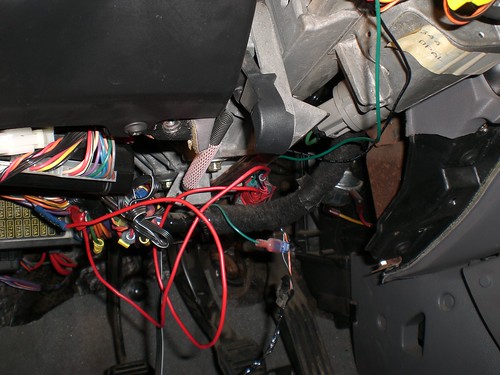
somewhere. In the pic below, you can see the wire,
it's a 14 gauge grey wire with a white stripe.
6. There won't be enough room here to cut the wire and
splice in two others, so follow the wire towards the
fuse box (near the fender), and you should find it
there with enough slack to work with. Don't worry,
there are no other wires just like it here, so it's
safe to cut this one. My car has an additional
security system, so there are more wires here than
yours will probably have, but you can see in the
picture here that I've cut the wire in half, and
already connected 1-1.5 feet of my 14 gauge wire to
the ignition side of the wire. Several different
methods of connecting your wires for this app include:
twisting and capping, twisting and soldering, using
other forms of connectors, or crimping on a coupler,
which is the most recommended (remember, for 14-gauge
wire, use blue or yellow couplers, not red, because
red is for smaller gauge wires).
7. Take the wire you just connected to the starter
wire on the ignition side, add your quick-disconnect
female connector to the end, and connect to #30 on
your relay, this will be the power lead end.
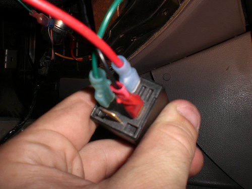
8. Repeat the process with the other end of the
starter wire and connect to #87 (remember, NOT 87a!)
on the relay, and you're pretty much done. The system
should work now, feel free to test it out!
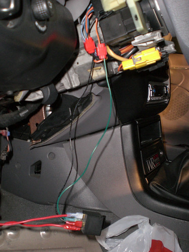
9. Now, place the relay in a secure position anywhere
behind the plastic panels. Be mindful of the steering
wheel tilt and make sure nothing interferes (you can
also screw the relay into one of the plastics,
preferably on the right, near the radio, but this
isn't necessary). I stashed mine right near the wiring
bundle that comes from the ignition.
10. Then, just put the plastics back in place, clean
up, and job complete. You've just installed a $6
security device, which would keep a thief occupied for
atleast a couple hours if they're patient and ballsey
enough to stick around and try to figure it out.
I give all credit for the idea for this project to
Steeda, I simply had the time to do it and take
pictures.
With this mod, you'll have to hold your bright flasher in so the brights are on in order for your starter to be able to be powered. This is a very effective, and cheap, way to secure your car from being stolen.
Pros: Cheap (around $6-$15), easy (takes about 45 minutes for a n00b), effective.
Cons: Telltale signs of security system for those who've seen your car start (they notice your brights are always on when you start your car), definitely a con for cons, though!
Items needed:
1 30 Amp auto 4 or 5 prong relay (Bosch design)
2 feet of 14 gauge automotive wire (preferably 2 colors)
2 feet of 18 gauge automotive wire (preferably 2 colors)
4 female quick disconnect connectors (for 14-18 gauge wiring)
2 14 gauge compatible wiring couplers (connects 2 wires)
2 wire taps (optional)
1. Remove the plastic case on the bottom side of the
steering column (where the ignition is) by removing
the 3 screws underneath it then gently pushing it out.
Locate the wires that come from the switch on the left
that controls the vehicles brights (blinkers also).
Find the orange wire with the yellow stripe, this is
the wire that gets power when you pull the handle to
flash your brights. If you're using wire taps, tap
into this wire with 1-1.5 feet of 18 gauge wire
(preferably green). Now, in the same bundle of wires,
find the black wire, we'll use this as the ground for
the relay coil, so tap into that with another 1-1.5
feet of 18 gauge wire (preferably black). If you're
not using wire taps, you can simply strip the wire and
pull back the insulation, then wrap your wire around
the exposed wiring. Soldering is recommended for that,
and electrical tape or heat shrinking is required.
This is what you should be looking at now:
2. Now, take the other ends of each of those wires,
and crimp on your female quick-disconnect connectors.
When we say "female" connector, this does relate to
human anatomy, so the female is the one that recieves
the male end of the connector. If the connector's
you're using aren't insulted, be sure to tightly and
thoroughly wrap them up with electrical tape after
crimping them on. Now, take your wire that's connected
to the orange/yellow one (mine's green), and put it on
the #85 prong of your relay (you may have to put a bit
for force to get the connector on there, but that's
good, that ensures a strong connection. If it's very
loose, that's bad).
Your relay maybe slightly different from mine. You may
have 5 prongs, where mine has four. The prongs are all
numbered, and the only ones you need to be concerned
with are 85, 86, 87, and 30. If yours has an 87a, just
use electrical tape to wrap it up.
3. Now, connect your black wire (the ground connected
to the black wire in the bundle) to the #86 on the
relay. Now, we've got the switch (headlight flasher)
wired into the coil of the relay. Now we just need to
attach the power for the device. First, we need to
remove that lower plastic panel. Start by twisting the
foot illumination light from behind and pull it out.
Then, using a small flat electronics screw driver or
razor blade, pop out the plastic covers over the top 3
bolts that hold tha panel on.
4. Then remove the top 3 and lower 2 bolts, which have
7mm heads. The panel should come right down. Once off,
check out the back of the ignition. It'll be a long
steel piece, which a black connector on the back. This
is where the starter wire comes from.
5. Now, what you want to do is cut the starter wire
somewhere. In the pic below, you can see the wire,
it's a 14 gauge grey wire with a white stripe.
6. There won't be enough room here to cut the wire and
splice in two others, so follow the wire towards the
fuse box (near the fender), and you should find it
there with enough slack to work with. Don't worry,
there are no other wires just like it here, so it's
safe to cut this one. My car has an additional
security system, so there are more wires here than
yours will probably have, but you can see in the
picture here that I've cut the wire in half, and
already connected 1-1.5 feet of my 14 gauge wire to
the ignition side of the wire. Several different
methods of connecting your wires for this app include:
twisting and capping, twisting and soldering, using
other forms of connectors, or crimping on a coupler,
which is the most recommended (remember, for 14-gauge
wire, use blue or yellow couplers, not red, because
red is for smaller gauge wires).
7. Take the wire you just connected to the starter
wire on the ignition side, add your quick-disconnect
female connector to the end, and connect to #30 on
your relay, this will be the power lead end.
8. Repeat the process with the other end of the
starter wire and connect to #87 (remember, NOT 87a!)
on the relay, and you're pretty much done. The system
should work now, feel free to test it out!
9. Now, place the relay in a secure position anywhere
behind the plastic panels. Be mindful of the steering
wheel tilt and make sure nothing interferes (you can
also screw the relay into one of the plastics,
preferably on the right, near the radio, but this
isn't necessary). I stashed mine right near the wiring
bundle that comes from the ignition.
10. Then, just put the plastics back in place, clean
up, and job complete. You've just installed a $6
security device, which would keep a thief occupied for
atleast a couple hours if they're patient and ballsey
enough to stick around and try to figure it out.
I give all credit for the idea for this project to
Steeda, I simply had the time to do it and take
pictures.
")